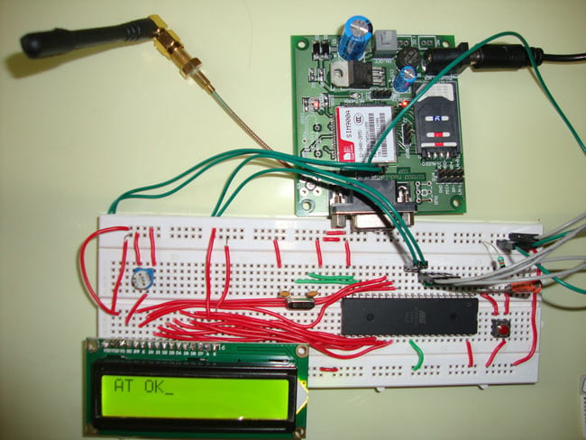
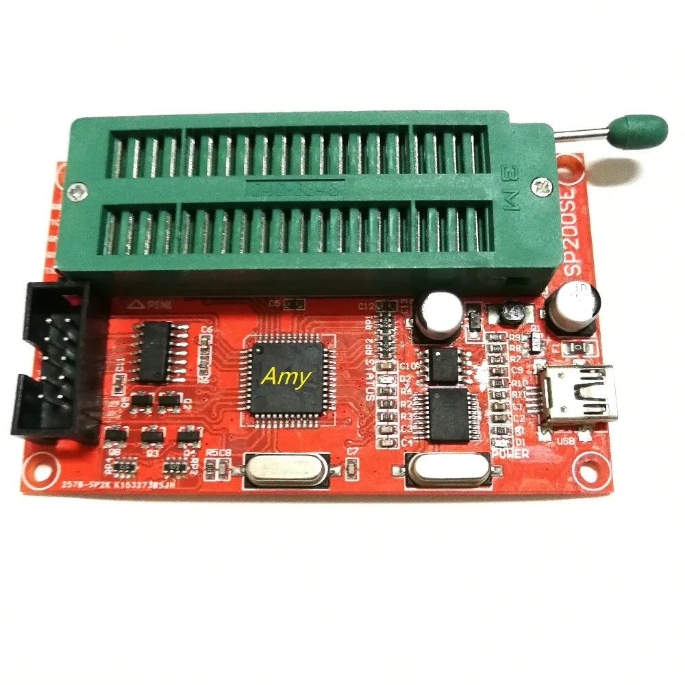
At89c2051 Programmer Using Usb To Serial Ttl

Single Sided Version I made this programmer on a single sided PCB only with both thru hole and surface mount components which I have lying around. This was originally made by Wichit Sirichote a few years back for his students but on a double sided PCB. More info can be found on his My Project files including the firmware, loader, PDF, and Eagle Files can be downloaded One of the problems on building this programmer is how to solve the chicken-egg problem, because the master MCU needs to be programmed first. You must find a friend who owns a programmer or have it programmed somewhere else. If you are from the Philippines I may help you build this programmer. Hello tiktakx, I am new to VB 2010 and I am having great problems getting started, in interfacing with VB.
I have looked all over the web, and bought books.but with very little success, I almost gave up.Then I found your site and the serial port prog, it’s brilliant!! It has helped me so much,and your step by step approach has made the subject much clearer.Do you have any code available to demonstrate to beginners like me,how instead of sending Text I could operate LED ‘s and read the inputs in binary. My ultimate aim is to make a control panel in VB to operate relays,solenoids, leds,etc and also read sensors and switches. Any Help you can give me will be very,very, appreciated.
Arduino USB 2 Serial Micro: This is the official Arduino brand USB-Serial converter and rather than being based on an FTDI chip, it uses an Atmega16u2 for the conversion, which is the same chip/circuit as found on the Uno, so you don't need to install the FTDI drivers and mentioned further down.
I would like your advice relating to using the Arduino IDE and avrdude to program an ATmega328 which is preloaded with an Arduino bootloader. I am using a USB to TTL-serial breakout board based on an FTDI chip. I bought a 'FTDI Basic Program Downloader USB to TTL FT232 for Arduino ACC' off I followed exactly this setup: • Connect the DTR pin to pin 1 on the ATmega through the 0.1uF capacitor. • Connect the RX pin to pin 3 on the ATmega (TX) • Connect the TX pin to pin 2 on the ATmega (RX) • Connect the 5V pin to the 5V rail of the board to supply the board with power from the USB interface.

• Connect the GND pin to the GND rail of the board () When I try uploading a sketch, I get this bad boy: avrdude: stk500_getsync(): not in sync: resp=0x00 Here's what I have tried so far: Connecting the header pins of the Arduino 'shield' to the chip on the breadboard. In doing so I am using the ATmega16U2 on board to send the program. Result: Flawless! The program boots and everyone is happy. Back to the FTDI breakout board.
3d qsar software testing tool. 3d-qsar The acronym 3D-QSAR or 3-D QSAR refers to the application of force field calculations requiring three-dimensional structures of a given set of small molecules with known activities (training set). QSAR and 3D QSAR in drug design Part 1: methodology Hugo Kubinyi Classical QSAR methods describe structure-activity relationships in terms of physicochemical parameters and steric properties (Hansch analysis, extrathermo- dynamic approach), or certain structural features (Free Wilson analysis).
 Nonton bokep ngentot kakak ipar Bokep Jepang Di Perkosa Tetangga Sampai Hamil; bokeo indo kawan lendir, bokep jav ngentot adik ipar sampai hamil, Download Bokep Gratis, Bokep Indo, Menikmati tubuh kakak ipar yang montok.
Switch RX and TX (never know?) still nothing so switched back to initial TX - RX configuration. The DTR pin out of the FTDI board is successfully resetting the ATmega328 for sure as it goes through its magical blinking sequence when I try to upload something.
Now, I've tested to see if the ATmega328 can send serial info through the breakout board to by computer. I've noticed a few interesting things: Both the TX and RX lines are always at 5 V. I know this because if I connect a LED in parallel with the lines, they light up.
But, the little tiny LEDs on the breakout board labeled TX and RX are not always on. Could that explain my problem? If you'd like any more info, let me know, I'll get it for you.
---------------------------------------------EDIT------------------------------------------ Hello again, OK I've added a 100uF electrolytic capacitor along with a 0.1uF one between 5v and GND. This isn't the suggested 47uF and 0.1uF but I guess it`ll help filter out none the less. ( while at it. What would it change?) I've replaced my 1k pull-up resistor with a 10k one I still am not able to upload a sketch and get the same error. DTR line calls a reset and I still get serial output.
(I have a sketch on it that sends incrementing integers through serial every second) Also interestingly, (although I was still unable to send a sketch before this happened) any LED I plug on pin 13 (aka 19) is now much dimmer. Maybe that utlra bright white LED I had earlier was pulling to much current with a 270 ohm resitor. -_- ) To popular demand here are pictures of my board and the USB to FTDI breakout board I am using. Couple of suggestions: Looking at the picture you appear to be following here: There is almost certainly an error which will cause Reset not to work as expected.